A proposal for building a telescope using a number of cylindrical/parabolic mirrors instead of spherical/parabolic mirrors. Bruno Postle, February 2001.
Description
This is an alternative method of constructing an optical system that involves the use of singly curved rather than doubly curved mirror surfaces. Traditional telescope optics typically use circular mirrors with a doubly curved synclastic parabolic shape. This system uses a pair of singly curved rectangular mirrors at right angles to each other to achieve the same effect.
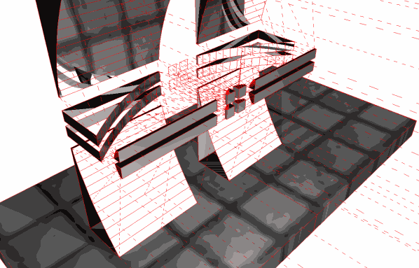
Figure 1. This is a model of the system shown as a fully symmetrical arrangement. In reality, the entire system is unlikely to be built like this, a more rational arrangement is shown in Figure 2. below.
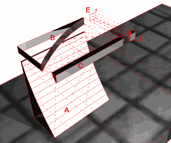
Figure 2. A simplified model of the system showing the minimum 4 mirrors. A is the concave primary collection mirror with a long focal-length Fp. C is a secondary convex linear mirror with a short focal length Fs parallel to A. B is a concave primary mirror with a long focal length Fp at 90° to primary mirror A. D is a convex secondary mirror with a short focal length Fs parallel to primary mirror B. E is the ‘camera’ viewpoint.
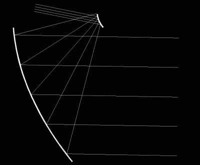
Figure 3. Section showing ray-paths in one plane of the system at 89° source angle.
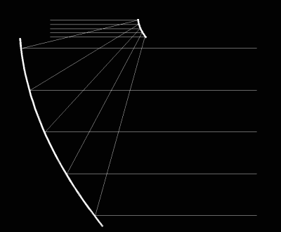
Figure 4. Section showing ray-paths in one plane of the system at 90° source angle.
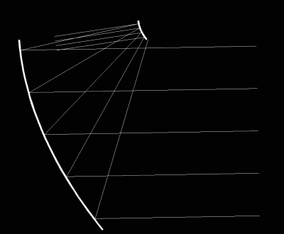
Figure 5. Section showing ray-paths in one plane of the system at 91° source angle.
Images taken using model telescope
These are pictures taken using the 3d computer model of the telescope in the images above – I haven't actually made a real prototype. The computer models (and resulting images) are a bit crude since the mirrors have to be made up from a finite number of flat strips simulating a truly curved surface.
Though the quality is not so good, they do demonstrate that the cylindrical-mirror arrangement is functionally equivalent to the spherical-mirror arrangement.
[ Update 2002-01-31: I've created some much higher quality versions of these images using a different model, they are a bit more convincing. You can also download the model I used. ]
These are pictures from a higher resolution raytrace model, the results are much more convincing.
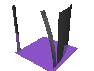
Figure 9. This is a model of the system .
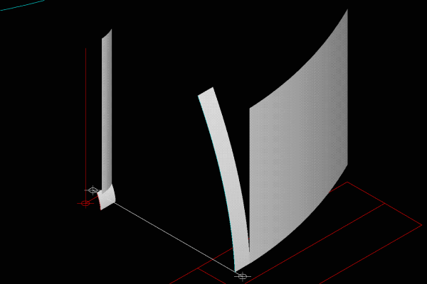
Figure 10. Another image of the same arrangement.
You can download the files used in this model (sorry, just AutoCAD-14 dwg format), if you want to play with it yourself.
Input image
Figure 11. This is the target image, placed at a distance in the model.
Output image
Figure 12. This is the output image, The smaller copies of the source image to the left and right are part of the target field. They are small because they are far away :-) . The central image is one of the target images scaled by the telescope arrangement.
Disadvantages
The light paths have to leave the optics in a parallel fashion. If you actually wanted to focus them as an image (rather than look through the thing), there would need to be additional lenses/mirrors.
Some of the light paths are very long, I haven't thought much about how this would affect things like the potential range of magnification, focal length etc.. presumably there would be limitations (which might make the whole scheme impractical of course).
Sheet materials are not really very useful, most have a ‘grain’ from the manufacturing process that would interfere with the optical quality.
Possible advantages
There is only one large surface area mirror (A) in this system, which can be constructed from sheet materials bent or formed into the parabolic shape required. All other mirrors in the system have negligible areas.
Simpler engineering. A traditional Newtonian telescope uses doubly curved spherical mirrors which behave unpredictably under stress (self weight and temperature loads both vary the focal length in different ways). Temperature stress causing expansion/contraction in a singly curved mirror need not cause any change in focal length or optical properties with suitably designed supports.
Dynamic shape change. The large primary mirror can be supported on a simple rectangular grid of adjustable supports. The supports can provide both micro adjustment/correction of small areas of the surface as well as macro adjustments to the focal length of the mirror as a whole.
Copyright © February 2001 Bruno Postle